


Setting & Operation
Status Monitor LED
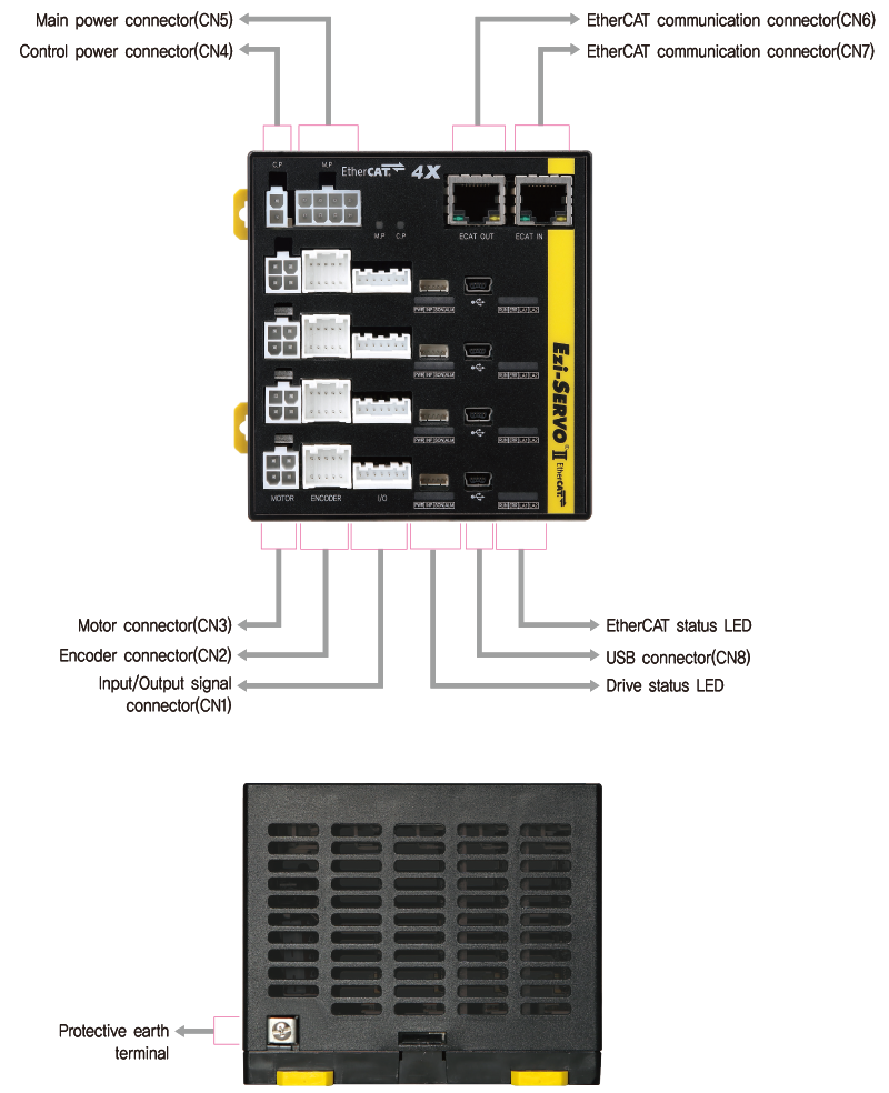
- 1. EtherCAT Status LED
- LED indicates communication status of EtherCAT.
-
Name Indication Color Status Explanation RUN Run Green OFF State INIT or Power OFF Blinking State PRE-OPERATIONAL Single Flash State SAFE-OPERATIONAL ON State OPERATIONAL Flickering State BOOTSTRAP Error ERR Red OFF No Error or Power OFF Blinking Invalid Configuration Single Flash Local Error Double Flash Watchdog Time Out Link /
ActivityLA1
LA2Green OFF Link not Established ON Link Established Flickering Link Established and in Operation 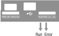
- 2. Drive Status LED
-
Indication Color Function ON/OFF Condition PWR Green Power input indication LED is turned ON when power is applied INP Yellow Complete Positioning Motion Lights On when Positioning error reaches within the preset pulse selected by parameter SON Orange Servo On / Off Indication Servo On: Lights On, Servo Off: Lights Off ALM Red Alarm Indication Flash when protection function is activated (Identifiable which protection mode is activated by counting the blinking times)
- ◆ Protection functions and LED flash times
-
Times Protection Conditions 1 Over Current Error The current through power devices in inverter exceeds 4.8A 2 Over Speed Error Motor speed exceeds 3,000 [rpm] 3 Position Tracking Error Position error value is higher than 90˚ in motor run state*1 4 Over Load Error The motor is continuously operated more than 5 seconds under a load exceeding the max. torque 5 Over Temperature Error Inside temperature of drive exceeds 85℃ 6 Over Regenerated Voltage Error Back-EMF more than 48V 7 Motor Connection Error The power is ON without connection of the motor cable to dreiv 8 Encoder Connect Error Cable connection error with Encoder connector in drive 9 Motor Power Error The input voltage of the motor power is too low or disconnected 10 In-Position Error After operation is finished, position error more than 1 pulse is continued for more than 3 seconds 12 ROM Error Error occurs in parameter storage device(ROM) 15 Position Overflow Error Position error value is higher than 90˚ in motor stop state*1 -
* 1 : Default value can be changed by parameter.(Refer to the Manual)
※ For the details, please refer to the Manual. -
Alarm LED flash
(Ex, Position tracking error)
Connector
- 1. Input/Output Signal Connector(CN1)
-
NO. Function I/O 1 EXT_24VDC Input 2 EXT_GND Input 3 LIMIT+ Input 4 LIMIT- Input 5 ORIGIN Input 6 BRAKE+ Output 7 BRAKE- Output 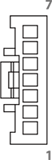
- 2. Encoder Connector(CN2)
-
NO. Function I/O 1 A+ Input 2 A- Input 3 B+ Input 4 B- Input 5 Z+ Input 6 Z- Input 7 5VDC Output 8 GND Output 9 F.GND ---- 10 F.GND ---- 
- 3. Motor Connector(CN3)
-
NO. Function I/O 1 A Phase Output 2 B Phase Output 3 / A Phase Output 4 / B Phase Output 
- 4. Control Power Connector(CN4)
-
NO. Function I/O 1 24VDC Input 2 GND Input 
- 5. Main Power Connector(CN5)
-
NO. Function I/O 1 24VDC Input 2 24VDC Input 3 24VDC Input 4 F.GND ---- 5 GND Input 6 GND Input 7 GND Input 8 F.GND ---- 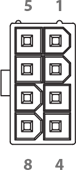
- 6. EtherCAT Communication Connector(CN6, CN7)
-
NO. Function 1 TD+ 2 TD- 3 RD+ 4 ---- 5 ---- -
NO. Function 6 RD- 7 ---- 8 ---- Connection
HoodF.GND 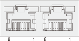
- 7. USB Connector(CN8)
-
NO. Function 1 VBUS 2 D- 3 D+ 4 ---- 5 GND 
Connector Specifications
- Connector specifications for cabling to drive.
-
Purpose Item Part Number Manufacturer Main Power
(CN5)Housing
Terminal5557-08R
5556TMOLEX Control Power
(CN4)Housing
Terminal5557-02R
5556TMOLEX Motor Drive Side
(CN3)Housing
Terminal5557-04R
5556TMOLEX Motor Side Housing
Terminal5557-04R
5556TMOLEX Encoder Drive Side
(CN2)Housing
Terminal51353-1000
56134-9000MOLEX Encoder Side Housing
TerminalSMP-09V-NC
SHF-001T-0.8BSJST Signal
(CN1)Housing
TerminalPAP-07V-S
SPHD-001T-P0.5JST - ※ Above Connector is the most suitable product for the drive applied. Another equivalent Connector can be used.