


Setting & Operation_ MPB Series
Status Monitor LED_ MPB Series
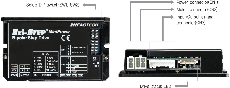
- 1. Drive Status LED
-
Indication Color Function ON/OFF Condition PWR Green Power Input Indication Lights when power is ON Flashes when motor is Free status ALM Red Alarm Indication Flash when protection function is activated (Identifiable which protection mode is activated by counting the flash times) CW Yellow Motor Rotation Direction Lights when motor rotate CW direction CCW Orange Motor Rotation Direction Lights when motor rotate CCW direction
- ◆ Protection functions and LED flash times
-
Times Protection Conditions 1 Over Current Error The current through power devices in drive exceeds the limit value*1 2 Over Speed Error Motor speed exceeded 3,000 [rpm] 3 Step Out Error Abnormally motor do not followed pulsed input 5 Over Temperature Error Internal temperature of a motor drive exceeded 85℃ 6 Over Regenerated Voltage Error Back EMF more than 50V 7 Motor Connection Error Power is ON without connection of motor cable to drive 9 Motor Voltage Error Motor voltage is below 20V 11 System Error Error occurs in drive system 12 ROM Error Error occurs in Parameter storage Device(ROM) -
- * 1 : Limit value depends on motor model (Refer to the Manual)
Alarm LED Flash
(Ex, Step Out Error)
Switch_ MPB Series
- 1. Stop Current Setting Switch(SW1.1~1.4)
- Stop Current means the motor current value automatically set in 0.1 sec after motor stops. This is to prevent the overheat of a motor when the motor is under long time idling. The unit of the selection value is a percentage.
-
Switch Position STOP Current (%) 4 3 2 1 ON ON ON ON 10 ON ON ON OFF 20 ON ON OFF ON 30 ON ON OFF OFF 40 ON OFF ON ON 50*1 ON OFF ON OFF 60 ON OFF OFF ON 70 ON OFF OFF OFF 80 OFF ON ON ON 90 OFF ON ON OFF 100 OFF ON OFF ON 10 OFF ON OFF OFF 10 OFF OFF ON ON 10 OFF OFF ON OFF 10 OFF OFF OFF ON 10 OFF OFF OFF OFF 10 -
- *1 : Default : 50%.
- 2. Resolution Setting Switch(SW1.5~1.8)
- The Number of pulse per revolution.
-
Switch Position Pulse/Revolution 8 7 6 5 ON ON ON ON 500 ON ON ON OFF 1,000 ON ON OFF ON 1,600 ON ON OFF OFF 2,000 ON OFF ON ON 3,200 ON OFF ON OFF 3,600 ON OFF OFF ON 4,000 ON OFF OFF OFF 5,000 OFF ON ON ON 6,400 OFF ON ON OFF 8,000 OFF ON OFF ON 10,000*1 OFF ON OFF OFF 20,000 OFF OFF ON ON 25,000 OFF OFF ON OFF 36,000 OFF OFF OFF ON 40,000 OFF OFF OFF OFF 50,000 -
- *1 : Default: 10,000
- 3. Rotational Direction Selection Switch(SW2.5)
-
Indication Switch Name Function DIR Switching Rotational Direction Based on CW(+Dir signal) input to drive.
· ON : CCW(-Direction)
· OFF : CW(+Direction)
※ Default : CW mode 
CCW Direction
Direction setting switch : ON
CW Direction
Direction setting switch : OFF
- 4. Pulse Input Selection Switch(SW2.6)
-
Indication Switch Name Function P Selecting Pulse Input Mode 1-Pulse Input Mode or 2-Pulse Input Mode
· ON : 1-Pulse Input Mode
· OFF : 2-Pulse Input Mode
※ Default : 2-Pulse mode 
Connector_ MPB Series
- 1. Power Connector(CN1)
-
No. Function I/O 1 24VDC Input 2 GND Input 
- 2. Motor Connector(CN2)
-
No. Function I/O 1 A Phase Output 2 B Phase Output 3 / A Phase Output 4 / B Phase Output 
- 3. Signal Connector(CN3)
-
No. Function I/O 1 CW+(Pulse+) Input 2 CW+(Pulse-) Input 3 CCW+(Dir+) Input 4 CCW-(Dir-) Input 5 EXT_GND Input -
No. Function I/O 6 EXT_24VDC Input 7 Alarm Reset Input 8 RUN/STOP Output 9 Alarm Output 10 F.GND ---- 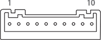
Connector Specifications
- Connector specifications for cabling to drive.
-
Purpose Item Part Number Manufacturer Power
(CN4)Housing
Terminal5557-02R
5556TMOLEX Motor Drive Side
(CN2)Housing
Terminal5557-04R
5556TMOLEX Motor Side Housing
Terminal5557-04R
5556TMOLEX Signal
(CN1)Housing
TerminalPAP-10V-S
SPHD-002T-P0.5JST - ※ Above connector is the most suitable product for the drive applied. Another equivalent connector can be used.
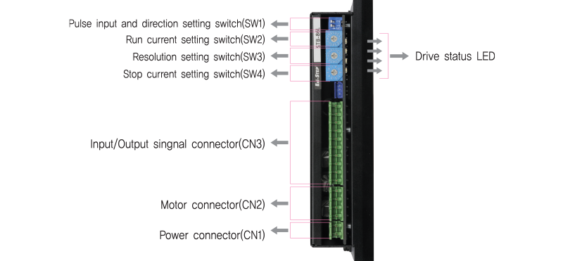
Setting & Operation_ HPB Series
Status Monitor LED_ HPB Series
- 1. LED Display
-
Indication Color Function Lighting Condition POW Green Power Input Indication Lights when power is ON Flashs when motor is Free status ALM Red Alarm Indication Flash when protection function is activated (Identifiable which protection mode is activated by counting the blinking times) CW Yellow Motor Rotation Direction Lights when motor rotate CW direction CCW Orange Motor Rotation Direction Lights when motor rotate CWW direction
- ◆ Protection functions and LED flash times
-
Times Protection Conditions 1 Over Current Error The current through power devices in drive exceeds the limit value**1 2 Over Speed Error Motor speed exceeded 3,000 [rpm] 3 Step Out Error Abnormally motor do not followed pulsed input 5 Over Temperature Error Internal temperature of a motor drive exceeded 85℃ 6 Over Regenerated Voltage Error Back EMF more than 90V 7 Motor Connection Error The power is ON without connection of the motor cable to drive 9 Motor Voltage Error Motor voltage is below 36V 11 System Error Error occurs in drive system 12 ROM Error Error occurs in parameter storage device(ROM) -
- * 1 : Limit value depends on motor model (Refer to the Manual)
Alarm LED flash
(Ex, Step Out Error)
Switch_ HPB Series
- 1. Pulse Input Setting Switch(SW1.1)
-
No. Switch Name Function 2P/1P Pulse input mode Select Switch Selectable 1-Pulse input mode or 2-Pulse input mode as Pulse input signal.
ON: 1-Pulse mode
OFF: 2-Pulse mode
※ Default: 2-Pulse mode
- 2. Rotational Direction Selection Switch(SW2.5)
-
Indication Switch Name Function DIR Rotational Direction Select Switch Based on CW(+Dir signal) input to driver
· ON : CCW(-Direction)
· OFF : CW(+Direction)
※ Default : CW mode CCW Direction
Direction setting switch : ONCW Direction
Direction setting switch : OFF
- 3. Run Current Selection(SW2)
- SW2 do not used in Ezi-STEP HPB.
- 4. Resolution Selection(SW3)
- The number of pulse per revolution.
-
Position Pulse/Revolution 0 500 1 1,000 2 1,600 3 2,000 4 3,200 5 3,600 6 4,000 7 5,000 -
Position Pulse/Revolution 8 6,400 9 8,000 A 10,000 B 20,000 C 25,000 D 36,000 E 40,000 F 50,000 -

- *1 : The default factory setting is 10,000.
- 5. Stop Current Selection(SW4)
- Stop Current means the motor current value automatically set in 0.1 sec after motor stops. This is to prevent the overheart of a motor when the motor is uder long time idling. The unit of the selection value is a percentage.
-
Position Stop Current(%) 0 10 1 20 2 30 3 40 4 50 -
Position Stop Current(%) 5 60 6 70 7 80 8 90 9 100 -

- *1 : The default factory setting is 50%.
Connector_ HPB Series
- 1. Power Connector(CN1)
-
No. Function I/O 1 GND Input 2 40~70VDC Input 
- 2. Motor Connector(CN2)
-
No. Function I/O 1 / B Phase Output 2 B Phase Output 3 / A Phase Output 4 A Phase Output 
- 3. Signal Connector(CN3)
-
No. Function I/O 1 F.GND ---- 2 EXT_GND Input 3 Alarm Output 4 RUN/STOP Output 5 Alarm Reset Input 6 EXT_24VDC Input 7 CCW-(Dir-) Input 8 CCW+(Dir+) Input 9 CW-(Pulse-) Input 10 CW+(Pulse+) Input 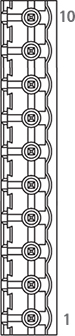
Connector Specifications
- Connector specifications for cabling to drive.
-
Purpose Item Part Number Manufacturer Power
(CN1)Terminal Block AK950-2 PTR Motor Drive Side
(CN2)Terminal Block AK950-4 PTR Motor Side Housing
Terminal3191-4R1
1381TMOLEX Signal
(CN3)Terminal Block AK950-10 PTR - ※ Above connector is the most suitable product for the drive applied. Another equivalent connector can be used.