


Settings and Operation

-
No. Name Function ① Status Indicator LED Indicates the status of the drive. ② USB Connector (CN5) Connects the drive to a PC. ③ Motor Sensor Connector (CN4) Connects the motor sensor. ④ Motor Connector (CN2) Connects the motor power. ⑤ Power / Regenerative Resistor Connector (CN1) Connects the main power supply and the regenerative resistor. ⑥ RS-485 Communication Connector (CN8 / CN9) Connects the RS-485 communication. ⑦ Slave Address Setting Switch (SW3) Sets the network slave address.
Max. 31 address can be set via combination with switch No.4 of Function Setting Switch (SW1).⑧ Termination Resistor Switch (SW2) Sets the termination resistor. ⑨ Function Setting Switch (SW1) Sets the baudrate and addritional functions. ⑩ Input/Output Signal Connector (CN7) Connects input/output signals.
Status Monitor LED
- 1. Status Indicator LED
-
Item Color Function Description Power LED Green Power Status Lights up when power is applied. Error LED Red Error Status Flashes when an error occurs. Communication LED Yellow RS-485 Comm. Status Flashes when the drive and the master communicate with RS-485. - ● List of Error Types by the Number of LED Blinking
-
No. Error Type Causes 1 Overcurrent Excessive current has flown through the drive. 2 Overspeed The rotation speed of the motor output shaft exceeds approx. 120 % of maximum speed. 5 Overtemperature When the internal temperature of the drive exceeds the allowable temperature. 6 Overvoltage When the back electromotive force of the motor increases and the motor driving voltage inside the drive exceeds the allowable rated voltage. 8 Hall sensor Error There is a problem with the connection between the drive and the motor sensor. 9 Undervoltage When the input power voltage is lower than allowable minimum voltage. 10 Initial Operation Inhibition Power is applied while the FWD or REV input is on. The error will be activated only if the ‘No Operation at Initial Run’ parameter is set to 1. 11 System error There is a problem in the internal circuit board. 12 ROM error The stored data is damaged or the read/write of the EEPROM is failed. 13 Motor parameter error When motor parameters are not set or are outside the normal range. 15 External stop error When EXT-ERROR input is executed in direct IO (operates when EXT-ERROR input is set in direct IO). 18 RS-485 Comm. Error The number of RS-485 comm. errors reaches the value set inn the ‘comm error alarm’ parameter. 19 RS-485 Comm. Time Out Communication is not established for the time set in ‘comm time out’ parameter.
Connector
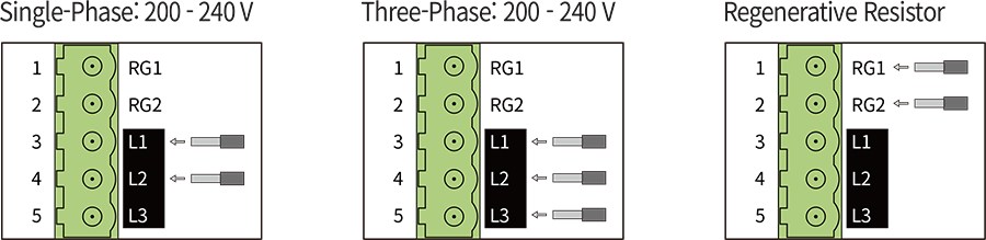
- 1. Power / Regenerative Resistor Connector(CN1)
-
No. Function 1 Regenerative Resistor Connection (RG1) 2 Regenerative Resistor Connection (RG2) 3 Power Input (L1) 4 Power Input (L2) 5 Power Input (L3) 
-
* Use RG1, RG2 terminals when connecting a regenerative resistor.
A regenerative resistor can be used when the deceleration time is short or the load with large inertia is applied.
* Please refer to the manual for details of regenerative resistor specifications. - ● Connection Method
- ● Wire Specifications
- AWG18 ~ 14(0.75 ~ 2.0mm2)
- 2. Motor Connector(CN2)
-
No. Function I/O 1 - - 2 BLDC_U Output Power 3 BLDC_W Output Power 4 BLDC_V Output Power 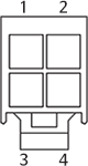
- 3. Motor Sensor Connector(CN4)
-
No. Function I/O 1 DC 5 V Output Power 2 GND Common 3 GND Common 4 HALL_U Input 5 HALL_V Input 6 HALL_W Input 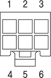
- 4. USB Connector(CN5)
-
No. Function 1 VBUS 2 D- 3 D+ 4 - 5 GND 
- USB Connector (CN5)
- Standard USB Cable (USB 2.0 Mini Type B)
- 5. Input/Output Signal Connector(CN7)
-
No. Function I/O 1 HCOM Input 2 IN0 Input 3 IN1 Input 4 IN2 Input 5 IN3 Input 6 IN4 Input 7 IN5 Input 8 IN6 Input 9 LCOM Common 10 OUT0+ Output 11 OUT0- Output 12 OUT1+ Output 13 OUT1- Output 14 VH Input 15 VM Input 16 VL Input 17 - - 18 - - 19 - - 20 - - 
- 6. RS-485 Communication Connector(CN8, CN9)
-
No. Function 1 GND 2 GND 3 Data+ 4 GND 5 GND 6 Data- 7 GND 8 GND 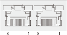
Accessories - Connectors
- These are connector specifications for drive cabling.
-
Purpose Item Part Number Manufacturer Power (CN1) Terminal Block CPF5.08-05P STELVIO Motor (CN2) Drive Side (CN2) Housing 5557-04R MOLEX Terminal 5556T Motor Side Housing 5559-04P MOLEX Terminal 5558T Sensor (CN4) Drive Side (CN4) Housing 5557-06R MOLEX Terminal 5556T Sensor Side Housing 5559-06P MOLEX Terminal 5558T Signal (CN7) Housing PADP-20V-1S JST Terminal SPH-002T-P0.5L