




Setting & Operation
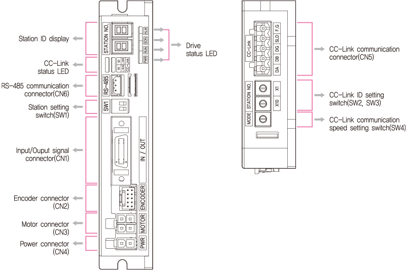
◆ 86mm Motor Drive(EzS2-CL-86 series)
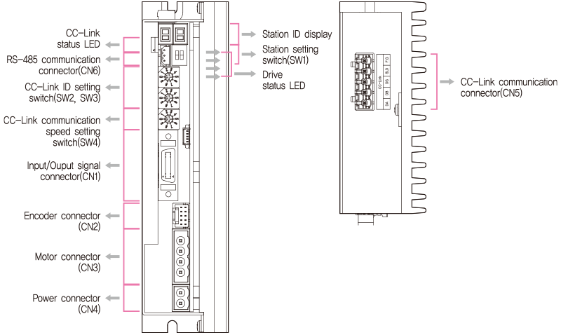
Status Monitor LED
- 1. CC-Link Status Monitor LED
-
Name Color Status Fuction Explanation L.
RunGreen Off Power OFF Checking the power status. No network connection Checking the status of the network cable and Master controller. On Normal operation CC-Link network connection is normal status. L.
ErrorRed Off Normal operation No error occurred On Critical error Communication process fails. Flashing Communication error Error occurred in the CC-Link network.
Check the 7-segment display information and process it.Random flashing CRC error, Network cable error There is a contact error of the network connector or noise in the cable line. To Check the terminating resistor attachment status, network wiring, and the grounding status of the frame. RD Orange Off No data receiving On Data recieving SD Yellow Off No data transmission On No data transmitting 
- 2. Status Monitor LED
-
Indication Color Function Lighting Condition PWR Green Power Input Indication LED is turned ON when power is applied INP Yellow Motor running indication LED is turned ON while motor is rotating SON Orange STEP On / Off indication STEP On: Lights On, STEP Off: Lights Off ALM Red Alarm Indication Flash when protection function is activated
- ◆ Protection functions and LED flash times
-
Times Error Code*3 Protection Conditions 1 E-□01 Over Current Error The current through power devices in inverter exceeds the limit value*1 2 E-□02 Over Speed Error Motor speed exceeds 3,000 [rpm] 5 E-□05 Over Temperature Error Temperature of inside of drive exceed 85℃ 6 E-□06 Over Regeneratived Voltage Error Back-EMF is higher than limit value*2 7 E-□07 Motor Connect Error The drive does STEP ON without connection of the motor cable to drive. 12 E-□0C ROM Error Error occurs in parameter storage device(ROM) -
* 1 : Limit value depends on motor model. (Refer to the Manual)
* 2 : Voltage limit of Back-EMP depends on motor model. (Reefr to the Manual)
* 3 : When an alarm occurs, error code is displayed on the 7-segment instead of CC-Link ID.
※ Please refer to the Manual for the details of protection functions.
※ □ is the CC-Link error code. -
Alarm LED flash
(Ex, Over Speed Error)
- ◆ CC-Link network status 7-segment display information
-
Error Code Description E-0 ☐ ☐ . Normal CC-Link network status E-1 ☐ ☐ . CC-Link station number switch setting is incorrect E-2 ☐ ☐ . CC-Link mode switch steeing is incorrect E-3 ☐ ☐ . CC-Link station number switch setting is changed E-4 ☐ ☐ . CC-Link mode switch steeing is changed E-5 ☐ ☐ . CRC error occurs in CC-Link communication E-6 ☐ ☐ . Timeout occurs during communication with master E-7 ☐ ☐ . Communication with master is disconnected E-8 ☐ ☐ . CC-Link Processor Error 1 E-9 ☐ ☐ . CC-Link Processor Error 2 E-A ☐ ☐ . Data link error E-B ☐ ☐ . Remote I/O error E-C ☐ ☐ . Remote register error - ※□□ is the drive error code.
Switch
- 1. CC-Link Station Display and Setting Switch(SW2, SW3)
- There are two Rotary switch to set value of CC-Link station No. Switch on the right side(×1) indicates the one’s(1) digit and Switch on the left side(×10) indicates ten’s(10) digit.

- ※ Default setting is ‘00’
- 2. CC-Link Communication Speed Setting Switch(SW4)
- This is a switch to set communication speed of CC-Link.
(The case of the product is marked with‘MODE’.) -
Mode CC-Link Baud Rate 0 156Kbps*1 1 625Kbps 3 2.5Mbps 4 5Mbps 5 10Mbps 6 None 7 None 8 None 9 None 
- * 1 : Defaule = 156kbps
- 3. CC-Link Station Setting Switch(SW1)
-
SW1.1 SW1.2 Occupation OFF OFF 1 Station occupation*1 ON OFF 2 Station occupation 
- * 1 : Defaule = ‘1 station occupation’
Connector
- 1. Input/Output Signal Connector(CN1)
-
No. Function I/O 1 LIMIT+ Input 2 LIMIT- Input 3 ORIGIN Input 4 Digital In1 Input 5 Digital In2 Input 6 Digital In3 Input 7 Digital In4 Input 8 Digital In5 Input 9 Digital In6 Input 10 Digital In7 Input -
No. Function I/O 11 Digital Out1 Output 12 Digital Out2 Output 13 Digital Out3 Output 14 Digital Out4 Output 15 Digital Out5 Output 16 Digital Out6 Output 17 BRAKE+ Output 18 BRAKE- Output 19 EXT_GND Input 20 EXT_24VDC Input 
- 2. Encoder Connector(CN2)
-
No. Function I/O 1 A+ Input 2 A- Input 3 B+ Input 4 B- Input 5 Z+ Input 6 Z- Input 7 5VDC Output 8 GND Output 9 F.GND ---- 10 F.GND ---- 
- 3. Motor Connector(CN3)
-
NO. Function I/O 1 A Phase Output 2 B Phase Output 3 / A Phase Output 4 / B Phase Output 
-
NO. Function I/O 1 / B Phase Output 2 B Phase Output 3 / A Phase Output 4 A Phase Output ※ 86mm motor drive.

- 4. Power Connector(CN4)
-
NO. Function I/O 1 24VDC Input 2 GND Input 
-
NO. Function I/O 1 GND Input 2 40~70VDC Input ※ 86mm motor drive.

- 5. CC-Link Communication Connector(CN5)
-
No. Function 1 DA 2 DB 3 DG 4 SLD 5 F.GND 
- 6. RS-485 Communication Connector(CN6)
-
No. Function 1 Data+ 2 Data- 3 GND 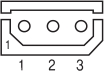
Connector Specifications
- Connector specifications for cabling to drive.
-
Purpose Item Part Number Manufacturer Power
(CN4)Housing
Terminal5557-02R
5556TMOLEX Motor Drive Side
(CN3)Housing
Terminal5557-04R
5556TMOLEX Motor Side Housing
Terminal5557-04R
5556TMOLEX Encoder Drive Side
(CN2)Housing
Terminal51353-1000
56134-9000MOLEX Signal
(CN1)Connector
Backshell10120-3000PE
10320-52A0-0083M CC-Link Communication
(CN5)Terminal Block AK950-5 PTR RS-485 Communication
(CN6)Housing
Terminal5264-03
5263PBTMOLEX - ※ Above Connector is the most suitable product for the drive applied. Another equivalent Connector can be used.
Connector Specifications_ 86mm
- Connector specifications for cabling to drive.
-
Purpose Item Part Number Manufacturer Power
(CN4)Terminal Block AK950-2 PTR Motor Drive Side
(CN3)Terminal Block AK950-4 PTR Motor Side Housing
Terminal3191-4R1
1381TMOLEX Encoder Drive Side
(CN2)Housing
Terminal51353-1000
56134-9000MOLEX Signal
(CN1)Connector
Backshell10120-3000PE
10320-52A0-0083M CC-Link Communication
(CN5)Terminal Block AK950-5 PTR RS-485 Communication
(CN6)Housing
Terminal5264-03
5263PBTMOLEX - ※ Above Connector is the most suitable product for the drive applied. Another equivalent Connector can be used.