


Setting & Operation
Status Monitor LED
- 1. Protection functions and 7-Segment flash times
-
Times Protection Conditions 1 Over Current Error The current through power devices in drive exceeds the limit value*1 2 Over Speed Error Motor speed exceeded 3,000 [rpm] 3 Step Out Error Abnormally motor do not followed pulsed input 5 Over Temperature Error Internal temperature of a motor drive exceeded 85℃ 6 Over Regenerated Voltage Error Back EMF more than 50V 7 Motor Connection Error Power is ON without connection of motor cable to drive 9 Motor Voltage Error Motor voltage is below 20V 11 System Error Error occurs in drive system 12 ROM Error Error occurs in Parameter storage Device(ROM) -
- * 1 : Limit value depends on motor model (Refer to the Manual)
7-Segment flash
(Ex, Step Out Error)
Switch
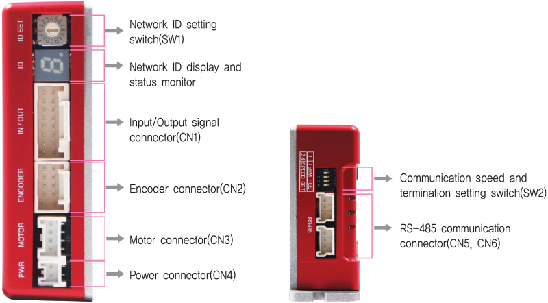
- 1. Network ID Setting Switch(SW1)
-
Position ID Number 0 0 1 1 2 2 3 3 4 4 5 5 6 6 7 7 -
Position ID Number 8 8 9 9 A 10 B 11 C 12 D 13 E 14 F 15 -
 ※ Maximum 16 axis can be connected in one network.
- 2. Communication Speed and Termination Setting Switch(SW2)
- Termination Setting Switch(SW2.1)
The drive installed at the end of the network must be terminated for reliable operation. Please termination setting switch is ON if drive install at the end of the network
Speed Setting Switch(SW2.2~SW2.4)
SW2.2~SW2.4 used for setting speed as follows -
SW2.1 SW2.2 SW2.3 SW2.4 Baud Rate [bps] - OFF OFF OFF 9,600 - ON OFF OFF 19,200 - OFF ON OFF 38,400 - ON ON OFF 57,600 - OFF OFF ON 115,200*1 - ON OFF ON 230,400 - OFF ON ON 460,800 - ON ON ON 921,600 -
 *1 : Default setting value
Connector
- 1. Motor Connector(CN3)
-
No. Function I/O 1 B Phase Output 2 / B Phase Output 3 / A Phase Output 4 A Phase Output 
- 1. Input / Output Signal Connector(CN1)
-
No. Function I/O 1 EXT_24VDC Input 2 EXT_GND Input 3 BRAKE+ Output 4 BRAKE- Output 5 LIMIT+ Input 6 LIMIT- Input 7 ORIGIN Input 8 Digital In1 Input -
No. Function I/O 9 Digital In2 Input 10 Digital In3 Input 11 Digital In4 Input 12 Digital In5 Input 13 Digital In6 Input 14 Digital In7 Input 15 Compare Out Output 16 Digital Out1 Output 
- 2. Encoder Connector(CN2)
-
No. Function I/O 1 A+ Input 2 A- Input 3 B+ Input 4 B- Input 5 Z+ Input -
No. Function I/O 6 Z- Input 7 5VDC Output 8 GND Output 9 F.GND ---- 10 F.GND ---- 
- 4. Power Connector(CN4)
-
No. Function I/O 1 24VDC Input 2 GND Input 
- 5. RS-485 Communication Connector(CN5, CN6)
-
No. Function 1 Data+ 2 Data- 3 GND 
Connector Specifications
- Connector specifications for cabling to drive.
-
Purpose Item Part Number Manufacturer RS-485 Communication
(CN5, CN6)Housing
Terminal35507-0300
50212-8100MOLEX Power
(CN4)Housing
TerminalPAP-02V-S
SPHD-001T-P0.5JST Motor
(CN1)Drive Side
(CN3)Housing
TerminalPAP-04V-S
SPHD-001T-P0.5JST Motor Side Housing
Terminal5557-04R
5556TMOLEX Encoder Drive Side
(CN2)Housing
Terminal501646-1000
501648-1000(AWG 26~28)MOLEX Signal
(CN1)Housing
Terminal501646-1600
501648-1000(AWG 26~28)MOLEX - ※ Above connector is the most suitable product for the drive applied. Another equivalent connector can be used.