Ezi-SERVOⅡ-BT-28 series
Input Signal
- Pulse input signals of the drive are all photocoupler protected. The signal shows the status of internal photocouplers [ON : Conduction], [OFF : Non-conduction], not displaying the voltage levels of the signal.

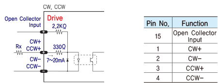
- ◆ CW, CCW Input
- This signal can be used to receive a positioning pulse command from a customer host motion controller. The customer can select 1-Pulse Input mode or 2-Pulse Input mode(refer to switch No.1, SW 1). The input schematic of CW, CCW is designed for 5V TTL level. When using 5V level as an input signal, the resistor Rx is not used and connect to the drive directly. When the level of input signal is more than 5V, Rx resistor is required. If the resistor is absent, the drive will be damaged! If the input signal level is 12V, Rx value is 680ohm and 24V, Rx value is 1.8Kohm.
- Servo On / Off and Alarm Reset of the drive are operated with voltage level [ON : High] and [OFF : Low].

- ◆ Servo On/Off Input
- This input can be used only to adjust the position by manually moving the motor shaft from the load-side. By setting the signal [LOW], the drive cuts off the power supply to the motor. Then, one can manually adjust output position. When setting the signal back to [High], the drive resumes the power to the motor and recovers the holding torque. When driving a motor, one needs to set the signal [High].
- ◆ Alarm Reset Input
- Release the alarm output of the drive where the protection function is activated. When the Alarm Reset input is set to [OFF], the alarm output is canceled. Remove the cause of the alarm before releasing the alarm output. If the cause of the alarm is not removed, the Alarm Reset input will not operate normally even if it is set to [OFF].

- ※ By setting the alarm reset input signal [ON], cancel the Alarm output. Before cancel the Alarm output, have to remove the source of alarm.
Output Signal
- Alarm and In-Position signals of the drive are operated by [ON : Conduction] and [OFF : Non-conduction] of open-drain circuit.

- ◆ Alarm Output
- The Alarm output indicates [ON] when the drive is in a normal operation. If a protection mode has been activated, it goes [OFF]. A host controller needs to detect this signal and stop sending a motor driving command. When the drive detects an abnormal operation such as overload or over current of the motor, it sets the Alarm output to [OFF], flashes the Alarm LED, disconnect the power to a motor and stops the motor simultaneously.
- ◆ In-Position Output
- The In-Position output is used to send motor motion to the host controller. When the movement of the motor is completed, the In-Position output becomes [ON]. In-Position output is [ON] when the motor stops within the position deviation set value.

Parameter Settings [Ezi-SERVOⅡ-BT-28 series]
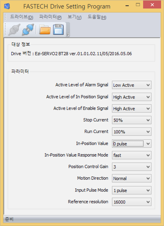
Parameter Settings GUI
(User Interface)
- Ezi-SERVOⅡ BT drive utilizes various parameters for operation and some parameters can be changed upon the needs of the user. Ezi-SERVOⅡ BT provides Drive Setting Program for more convenient use. The screen shot in right side is the sample of Drive Setting Program which is used for drive setting and parameter change. User can change and set the parameter such as level of Alarm Reset, Alarm, In-Position Signal, Enable signal and so on. By using this drive setting program, user can find the optimal condition to Ezi-SERVOⅡ BT to fit with the user’s own system. Please be noticed that connection for drive setting program shall be done when the Ezi-SERVOⅡ BT is disable staus for safety reason.
-
※ Graphic User Interface(GUI) Program can be downloaded from website. (www.fastech-motions.com)
※ Graphic User Interface(GUI) Program can support Window 7/8/10.
※ Graphic User Interface(GUI) Program can be update without prior notice for improving the performance or convenience of user.
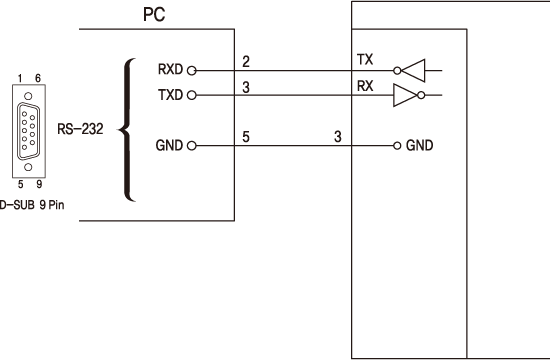
Parameter Settings wiring Diagram
(Ezi-SERVOⅡ-BT-28 Series)

Ezi-SERVOⅡ-BT-42/56/60 series
Input Signal
- Input signals of the drive are all photocoupler protected. The signal shows the status of internal photocouplers [ON: conduction], [OFF: Non-conduction], not displaying the voltage levels of the signal.
- ◆ CW, CCW Input
- This signal can be used to receive a positioning pulse command from a user host motion controller. The user can select 1-pulse input mode or 2-pulse input mode (refer to switch No.1, SW1). The input schematic of CW, CCW is designed for 5V TTL level. When using 5V level as an input signal, the resistor Rx is not used and connect to the driver directly. When the level of input signal is more than 5V, Rx resistor is required. If the resistor is absent, the drive will be damaged. If the input signal level is 12V, Rx value is 680ohm and 24V, Rx value is 1.8Kohm.

- ◆ Servo On/Off Input
- This input can be used only to adjust the position by manually moving the motor shaft from the load-side. By setting the signal [ON], the driver cuts off the power supply to the motor. Then, one can manually adjust output position. When setting the signal back to [OFF], the driver resumes the power to the motor and recovers the holding torque. When driving a motor, one needs to set the signal [OFF].
- ◆ Alarm Reset Input
- When a protection mode has been activated, a signal to this alarm reset input cancels the Alarm output.
- ※ By setting the alarm reset input signal [ON], cancel the Alarm output. Before cancel the Alarm output, have to remove the source of alarm.
Output Signal
- Output signals from the driver are photocoupler protected: Alarm, In-Position and the Line Driver Outputs (encoder signal). In the case of photocoupler outputs, the signal indicates the status of internal photocouplers [ON: conduction], [OFF: Non-conduction], not displaying the voltage levels of the signal.

- ◆ Alarm Output
- The Alarm output indicates [ON] when the driver is in a normal operation. If a protection mode has been activated, it goes [OFF]. A host controller needs to detect this signal and stop sending a motor driving command. When the driver detects an abnormal operation such as overload or over current of the motor, it sets the Alarm output to [OFF], flashes the Alarm LED, disconnect the power to a motor and stops the motor simultaneously.
- [Caution] Only at the Alarm output port, the photocoupler isolation is in reverse. When the driver is in normal operation the Alarm output is [ON]. On the contrary when the driver is in abnormal operation that start protection mode, the Alarm output is [OFF].
- ◆ In-Positio Output
- In-Position signal is [ON] when positioning is completed. This signal is [ON] when the motor

- ◆ Encoder Signal Output
- The encoder signal is a line driver output. This can be used to confirm the stop position.
Parameter Settings [Ezi-SERVOⅡ-BT-42/56/60 series]
Parameter Setting GUI
(User Interface)
-
Ezi-SERVOⅡ BT driver utilizes various parameters for operation.
Some parameters need to be adjusted once users feel inconvenience to use or in order to maximize efficiency. Ezi-SERVOⅡ BT provides parameter modification program for convenience of product usage for users.
The screen shot as below is computer program (GUI) which used for operation process. Users can change and set the parameters of drive for Enable Level, Alarm Reset Level, In-Position Level, Alarm Output Level. Users can use Ezi-SERVOⅡ BT according to its own system.
Please connect parameter setting GUI when Ezi-SERVOⅡ BT is Disable state. For safety reason, Ezi-SERVOⅡ BT can not be connected to setting GUI when it is Enable state. -
※ Graphic User Interface(GUI) Program can be downloaded from website. (www.fastech-motions.com)
※ Graphic User Interface(GUI) Program can support Window 7/8/10.
※ Graphic User Interface(GUI) Program can be update without prior notice for improving the performance or convenience of user.
Parameter Settings wiring Diagram
(Ezi-SERVOⅡ-BT-28 Series)