


Setting & Operation
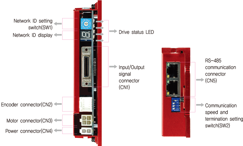
◆ 86mm Motor Drive(EzS-NDR-86 series)
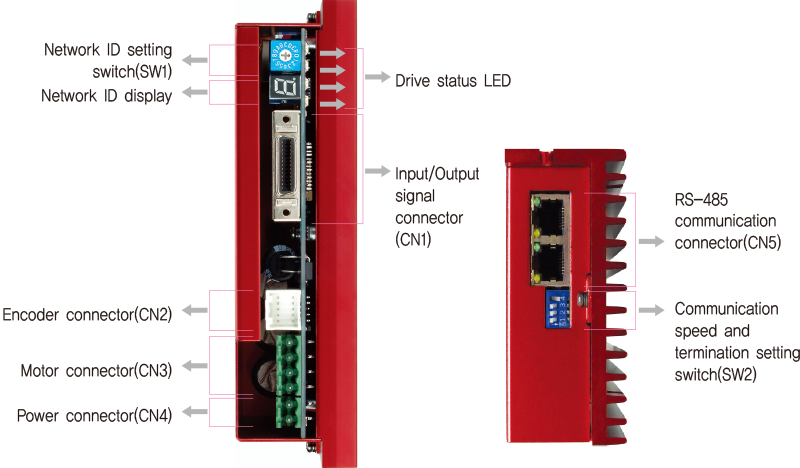
Status Monitor LED
- 1. LED Display
-
Indication Color Function ON/OFF Condition PWR Green Power Input Indication LED is turned ON when power is applied INP Yellow Complete positioning motion Lights On when Positioning error reaches within the preset pulse selected by parameter SON Orange Servo On/Off Indication Servo On: Lights On, Servo Off: Lights Off ALM Red Alarm Indication Flash when protection function is activated(Identifiable which protection mode is activated by counting the blinking times)
- ◆ Protection functions and LED flash times
-
Times Protection Conditions 1 Over Current Error The current through power devices in drive exceeds the limit value*1 2 Over Speed Error Motor speed exceeds 3,000 [rpm] 3 Position Tracking Error Position error value is higher than 180˚ in motor run state*2 4 Over Load Error The motor is continuously operated more than 5 seconds under a load exceeding the max. torque 5 Over Temperature Error Inside temperature of drive exceeds 85℃ 6 Over Regenerated Voltage Error Back-EMF is higher than limit value*3 7 Motor Connection Error The power is ON without connection of the motor cable to dreiv 8 Encoder Connect Error Cable connection error in Encoder connection of drive 10 In-Position Error After operation is finished, position error more than 1 pulse is continued for more than 3 second 11 System Error Error occurs in drive system 12 ROM Error Error occurs in parameter storage device(ROM) 15 Position Overflow Error Position error value is higher than 180˚ in motor stop state*2 -
* 1 : Limit value depends on motor model(Refer to the Manual)
* 2 : Limit value can be change by parameter
* 3 : Voltage limit of Back-EMF depends on motor model (Refer to the Manual)
※ For the details, please refer to the Manual.Alarm LED flash
(Ex : Position Tracking Error)
Switch
- 1. Network ID Setting Switch(SW1)
-
Position ID Number 0 0 1 1 2 2 3 3 4 4 5 5 6 6 7 7 -
Position ID Number 8 8 9 9 A 10 B 11 C 12 D 13 E 14 F 15 -
 ※ Maximum 16 axis can be connected in one network.
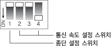
- 2. Communication Speed and Termination Setting Switch(SW2)
- Termination Setting Switch(SW2.1)
The drive installed at the end of the network must be terminated for reliable operation. Please termination setting switch is ON if drive install at the end of the network.
Speed Setting Switch(SW2.2~SW2.4)
SW2.2~SW2.4 used for setting speed as follows. -
SW2.1 SW2.2 SW2.3 SW2.4 Baud Rate [bps] - OFF OFF OFF 9,600 - ON OFF OFF 19,200 - OFF ON OFF 38,400 - ON ON OFF 57,600 - OFF OFF ON 115,200*1 - ON OFF ON 230,400 - OFF ON ON 460,800 - ON ON ON 921,600 -
 *1 : Default setting value
Connector
- 1. Input/Output Signal Connector(CN1)
-
No. Function I/O 1 LIMIT+ Input 2 LIMIT- Input 3 ORIGIN Input 4 Digital In1 Input 5 Digital In6 Input 6 Digital In7 Input 7 Compare Out Output 8 Digital Out1 Output 9 Digital Out2 Output 10 Digital Out3 Output 11 Digital Out4 Output 12 Digital Out5 Output 13 Digital Out6 Output -
No. Function I/O 14 Digital In2 Input 15 Digital In3 Input 16 Digital In4 Input 17 Digital In5 Input 18 Digital In8 Input 19 Digital In9 Input 20 Digital Out7 Output 21 Digital Out8 Output 22 Digital Out9 Output 23 BRAKE+ Output 24 BRAKE- Output 25 EXT_GND Input 26 EXT_24VDC Input 
- 2. Encoder Connector(CN2)
-
No. Function I/O 1 A+ Input 2 A- Input 3 B+ Input 4 B- Input 5 Z+ Input 6 Z- Input 7 5VDC Output 8 GND Output 9 F.GND --- 10 F.GND --- 
- 3. Motor Connector(CN3)
-
No. Function I/O 1 A Phase Output 2 B Phase Output 3 / A Phase Output 4 / B Phase Output 
-
No. Function I/O 1 / B Phase Output 2 B Phase Output 3 / A Phase Output 4 A Phase Output ※ Only for 86mm motor drive.

- 4. Power Connector(CN4)
-
No. Function I/O 1 24VDC Input 2 GND Input 
-
No. Function I/O 1 GND Input 2 40~70VDC Input ※ Only for 86mm motor drive.

- 5. RS-485 Communication Connector(CN5)
-
No. Function 1 GND 2 GND 3 Data+ 4 GND 5 GND -
No. Function 6 Data- 7 GND 8 GND LED 1, 3 Drive status LED 2, 4 Communication status 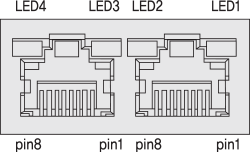
Connector Specifications
- Connector specifications for cabling to drive.
-
Purpose Item Part Number Manufacture Power
(CN4)Housing
Terminal5557-02R
5556TMOLEX Motor Drive Side
(CN2)Housing
Terminal5557-04R
5556TMOLEX Motor Side Housing
Terminal5557-04R
5556TMOLEX Encoder Drive Side
(CN2)Housing
Terminal51353-1000
56134-9000MOLEX Encoder Side Housing
TerminalSMP-09V-NC
SHF-001T-0.8BSJST Signal
(CN1)Connector
Backshell10126-3000PE
10326-52F0-0083M - ※ Above connector is the most suitable product for the drive applied. Another equivalent connector can be used.
Connector Specifications_ 86mm
- Connector specifications for cabling to drive.
-
Purpose Item Part Number Manufacture Power
(CN4)Terminal Block AK950-2 PTR Motor Drive Side
(CN2)Terminal Block AK950-4 PTR Motor Side Housing
Terminal3191-4R1
1381TMOLEX Encoder Drive Side
(CN2)Housing
Terminal51353-1000
56134-9000MOLEX Encoder Side Housing
TerminalSMP-09V-NC
SHF-001T-0.8BSJST Signal
(CN1)Connector
Backshell10126-3000PE
10326-52F0-0083M - ※ Above connector is the most suitable product for the drive applied. Another equivalent connector can be used.